Single half-wave rectifier circuit
AC to pulsating DC


A half-wave rectifier is a circuit that converts an AC voltage into a pulsating DC voltage by allowing only one half-cycle of the input waveform to reach the load. Depending on the diode orientation, either the positive or the negative half-cycles can be delivered to the load.
The circuit is very simple and requires only a few components:
- an AC voltage source, such as a transformer secondary winding or a function generator;
- one silicon PN-junction diode, in this case a 1N4007;
- one load to be supplied with DC voltage, in this case a resistor;
- one smoothing capacitor, whose value must be selected according to the desired ripple.
Before proceeding, the following basic knowledge is useful:
- diode theory;
- use of a multimeter;
- basic oscilloscope operation.
 |
 |
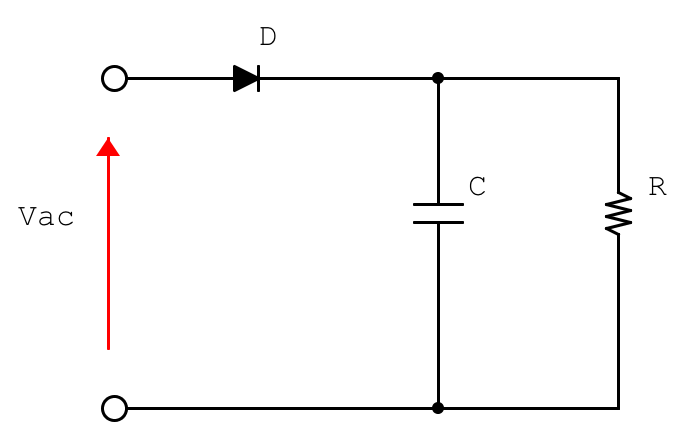
First, let us consider the circuit diagram. The AC supply voltage, with frequency \(f\), reaches the load \(R_L\) through the diode \(D\). A capacitor \(C\) may be connected in parallel with the load in order to smooth the output voltage.
At this point, two theoretical concepts must be recalled.
A diode is a nonlinear passive component that allows current to flow mainly in one direction. When it is forward-biased and the input voltage exceeds its forward voltage drop, the diode conducts. In this circuit, the diode is oriented so that only the positive half-cycles of the input signal reach the load.
A capacitor is a component that stores electric charge and can release it later. In this application, the capacitor charges during the conducting part of the waveform and discharges through the load when the diode is not conducting. This charge-discharge process reduces the output voltage ripple and makes the voltage across the load more similar to a DC voltage.
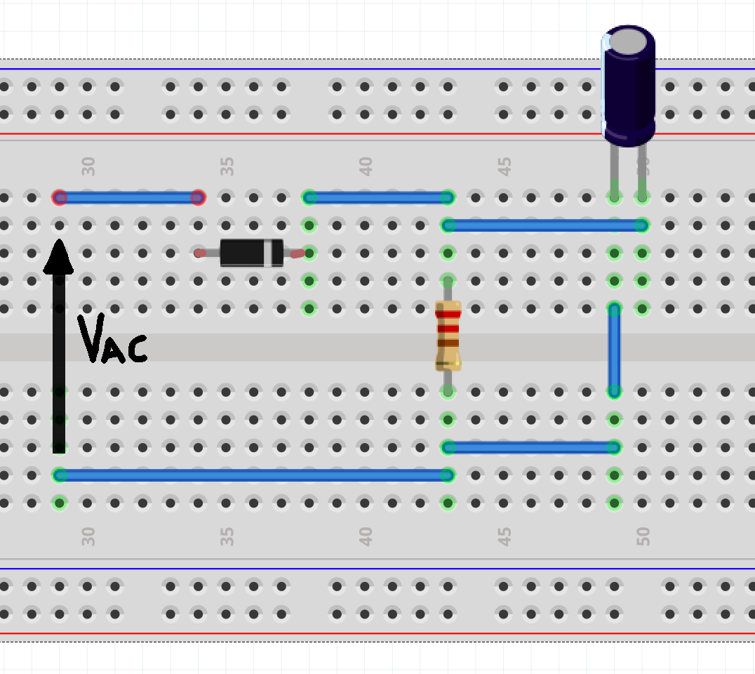
Note: when using electrolytic capacitors, polarity must be respected.
Main Quantities for a Half-Wave Rectifier
For an ideal half-wave rectifier without a smoothing capacitor, the following quantities can be defined.
The average no-load output voltage is:
\(V_{O,DC}=\frac{V_{MAX}}{\pi}\)where \(V_{MAX}\) is the peak value of the AC input voltage.
The maximum forward current through the diode is approximately:
\(I_{FM}=\frac{V_{MAX}}{R_L}\)The average forward current through the diode is:
\(I_{F(AV)}=\frac{V_{MAX}}{\pi R_L}\)The maximum reverse voltage across the diode, without a smoothing capacitor, is approximately:
\(V_{RRM}=V_{MAX}\)When a smoothing capacitor is connected, the peak inverse voltage across the diode can become higher and may approach approximately:
\(V_{RRM}\approx 2V_{MAX}\)This is important when selecting the diode voltage rating.
Measurement Without the Smoothing Capacitor
First, the capacitor is removed in order to observe the basic rectifying action of the diode.
For the test, the following components and settings were used:
- load resistor: \(220\,k\Omega\);
- no smoothing capacitor;
- diode: 1N4007;
- function generator voltage: \(8.9\,V_{pp}\);
- frequency: \(50\,Hz\).
By connecting one oscilloscope probe to the input voltage and another probe to the load voltage, the rectified waveform can be observed.
The load receives only the positive half-cycle of the input waveform. The positive peak voltage across the load is slightly lower than the input peak voltage because of the forward voltage drop of the diode.
For example, if the oscilloscope shows a difference of approximately 0.3 divisions and the vertical scale is:
\(\frac{Volts}{div}=2V\)the voltage drop is approximately:
\(\Delta V=0.3\cdot 2=0.6V\)This value is consistent with the typical forward voltage drop of a silicon diode operating at low current.
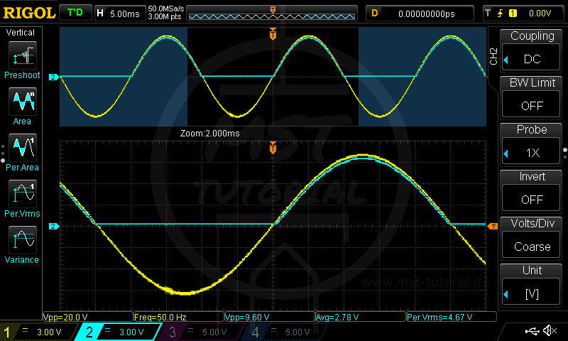
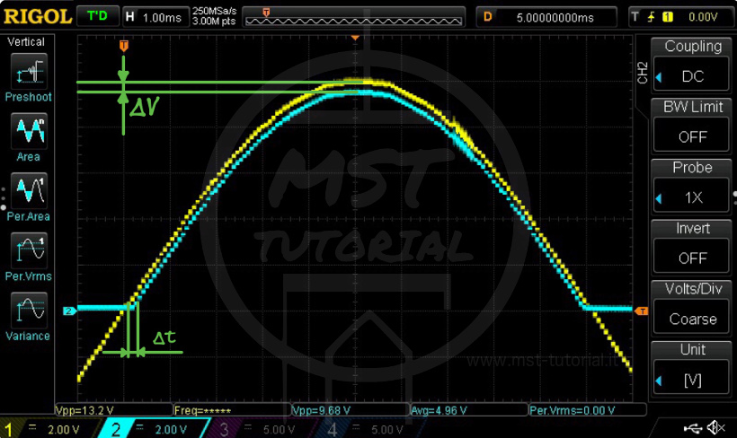
It can also be observed that the diode does not conduct immediately at the zero crossing. Instead, conduction starts only when the input voltage becomes high enough to forward-bias the diode. This creates a short interval before conduction begins.
If the oscilloscope time scale is:
\(\frac{Time}{div}=1ms\)and the measured delay is about 0.3 divisions, then:
\(\Delta t=0.3\cdot 1=0.3ms\)However, this delay should not be interpreted as a fixed delay introduced by the diode. It depends on the input waveform amplitude, the diode forward voltage, and the load conditions.
Finally, it is clear that the load is not supplied for approximately half of each period. Therefore, this type of rectified voltage is not suitable for sensitive loads if used without filtering, because the voltage varies continuously from 0 V to the positive peak value.
Mathematical Analysis
Starting from a measurement taken with the oscilloscope set to:
\(\frac{Volts}{div}=5V\)and:
\(\frac{Time}{div}=5ms\)the input supply voltage is measured as:
\(V_{pp}=20.2V\)For a sinusoidal AC voltage centered around zero, the positive peak value is:
\(V_P=\frac{V_{pp}}{2}=\frac{20.2}{2}=10.1V\)The RMS value of the sinusoidal input voltage is:
\(V_{RMS}=\frac{V_P}{\sqrt{2}}=\frac{10.1}{\sqrt{2}}=7.14V\)Since the input is an alternating sinusoidal signal with no DC offset, its average value over a full period is:
\(V_{AVG}=0V\)Now let us analyze the rectified voltage across the load, without any smoothing capacitor.
If the positive peak value measured across the load is approximately:
\(V_P=9.8V\)then the RMS value of an ideal half-wave rectified sine wave is:
\(V_{RMS}=\frac{V_P}{2}=\frac{9.8}{2}=4.9V\)The average value is:
\(V_{AVG}=\frac{V_P}{\pi}=\frac{9.8}{\pi}=3.11V\)Effect of the Smoothing Capacitor
A smoothing capacitor can now be connected in parallel with the load.
The smoothing effect depends on the capacitance value. A small capacitor discharges quickly between consecutive peaks, producing a large ripple voltage. A larger capacitor stores more charge and discharges more slowly, producing a smoother output voltage.
As the capacitance increases:
- the ripple voltage decreases;
- the average output voltage increases;
- the output voltage becomes more similar to a DC voltage.
The approximate ripple voltage for a half-wave rectifier with a smoothing capacitor can be estimated by:
\(V_{ripple}\approx\frac{I_L}{fC}\)where:
- \(I_L\) is the load current;
- \(f\) is the input frequency;
- \(C\) is the smoothing capacitance.
For a half-wave rectifier, the capacitor is recharged once per input period, so the ripple frequency is equal to the supply frequency.
Experimental Results with Different Capacitors
\(C=10nF\), \(D=1N4007\), \(R=100k\Omega\)
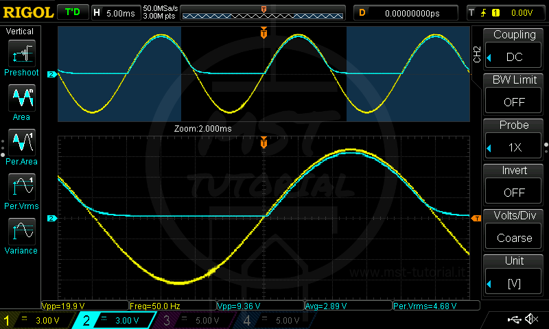
The smoothing effect is very weak. The capacitor discharges quickly, and the load remains almost unsupplied for a significant portion of the period.
\(C=100nF\), \(D=1N4007\), \(R=100k\Omega\)
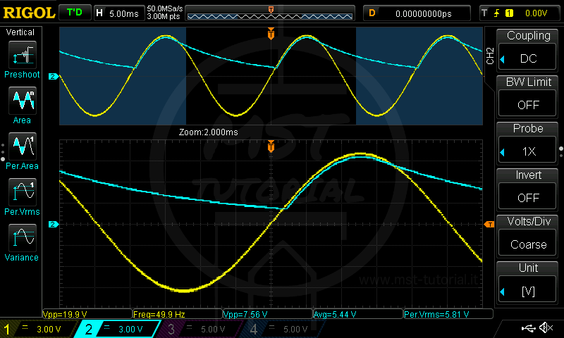
The capacitance is sufficient to prevent the output voltage from falling to zero, but the smoothing is still poor. The load is continuously supplied, but the voltage has significant fluctuations, with a ripple of approximately \(6V_{pp}\).
\(C=1000nF\), \(D=1N4007\), \(R=100k\Omega\)
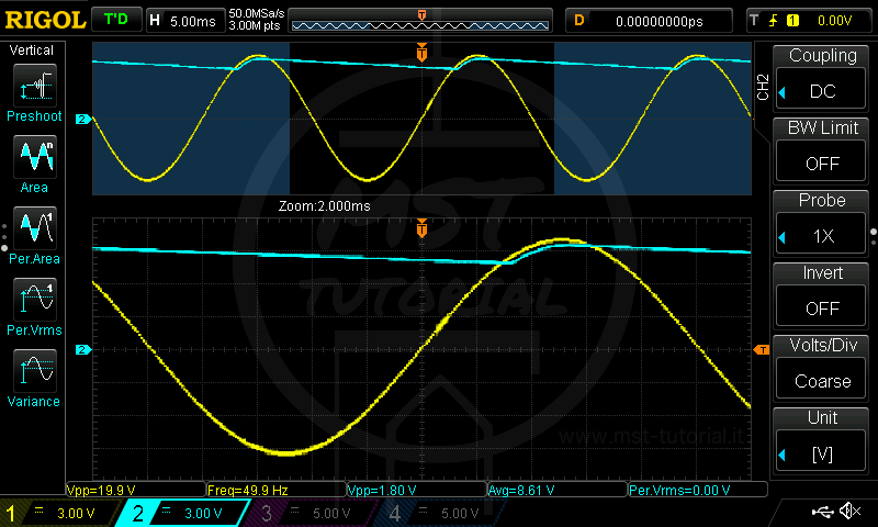
The smoothing effect is moderate. The output voltage still fluctuates, but the ripple is reduced to approximately \(1.8V_{pp}\).
\(C=10000nF=10\mu F\), \(D=1N4007\), \(R=100k\Omega\)
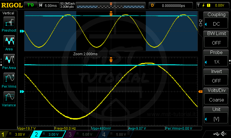
The capacitance provides good smoothing. The load voltage is much more stable, although a residual ripple of approximately \(0.48V_{pp}\) is still present.
Form Factor and Ripple Factor
The form factor, indicated as \(K_f\), is defined as the ratio between the RMS value and the average value of a waveform:
\(K_f=\frac{V_{RMS}}{V_{AVG}}\)For a half-wave rectified sinusoidal voltage without a smoothing capacitor and with a purely resistive load:
\(K_f=\frac{\frac{V_P}{2}}{\frac{V_P}{\pi}}\)Therefore:
\(K_f=\frac{\pi}{2}=1.57[/LATEX]From the form factor, the ripple factor [latex]r\) can be calculated as:
\(r=\sqrt{K_f^2-1}\)Thus:
\(r=\sqrt{1.57^2-1}=1.21\)When a capacitor is connected in parallel with the load, the DC component of the output voltage increases and the AC ripple component decreases. As a result, the ripple factor decreases.
The closer the ripple factor is to zero, the better the smoothing action of the rectifier circuit.